使用pspice的交流电源信号的频率相关开关模型
专为 PSpice 仿真设计的频率相关开关使专家能够解决高级系统中的挑战,无缝集成到各种电子电路中。
开关可用于 UHF 或更高无线电频段中需要通过多个路径路由信号的任何设备/电路。ATE(自动测试设备)系统中使用不同配置的开关。固态开关可分为两大类:机械式、继电器式、PIN 二极管和 FET。他们可以使用,
要在双输出之间切换单个信号,
要连接不同的多个输出,将信号并联到端口连接,
绕着电路元件或系统路由更改(旁路)电压,而不是通过电路元件或系统。
通过频域中的示例描述了与 PSpice 电路仿真软件兼容的电压/电流控制模拟行为模型开关的设计和建模。
模拟方法
描述了使用模拟行为建模获得不同开关的等效电路的 PSpice 方法。该领域的其他工作使用原始 PSpice 程序的多项式电压/电流源模型使用不同的配置。
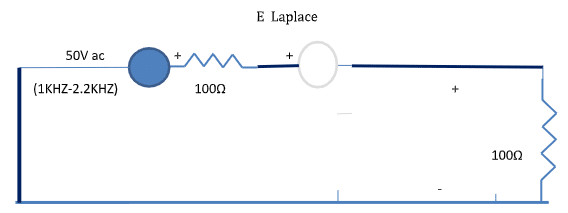
图 1 包含拉普拉斯开关 (E) 和电阻器的线性高功率网络
图 2:带有频率相关开关 S1 的线性有源高功率网络
表 I 描述了(图 1)获得频率依赖性的 PSpice 程序,该程序在 1700Hz 时表现为短,在图 1 的其他工作频率下变为开路 [相当于执行开关(开/关)动作]。图 1 中的 E 拉普拉斯描述了使用带有拉普拉斯选项的 PSpice 模拟行为模型的开/关电阻器。
Table I. Frequency description of switch operation (Fig: 1)
| **** 10/03/23 16:43:29 ****** PSpice Lite (October 2012) ****** ID# 10813 **** |
| Frequency-dependent switch simulation |
| Circuit description |
| V2 1 0 AC 1 |
| R13 1 3 100 |
| E34 3 4 LAPLACE {I(E34)} = {(ABS(S)/(2.0*3.141592653589793)-1700)*1E8} |
| R40 4 0 100 |
| .AC LIN 13 1KHz 2.2KHz |
| .PRINT AC VM(1) VM(3) VM(4) |
| .OP |
| .end |
| **** 10/03/23 16:43:29 ****** PSpice Lite (October 2012) ****** ID# 10813 **** |
| Frequency-dependent switch simulation |
| Small signal bias solution Temperature = 27.000 DEG C |
| Node voltage |
| ( 1) 0.0000 ( 3) 0.0000 ( 4) 0.0000 |
| Voltage source currents |
| Name Current |
| V2 0.000E+00 |
| Total power dissipation 0.00E+00 watts |
| **** 10/03/23 16:43:29 ****** PSpice Lite (October 2012) ****** ID# 10813 **** |
| Frequency-dependent switch simulation |
| Operating point information Temperature = 27.000 DEG C |
| Voltage-controlled voltage sources |
| Name E34 |
| V-source 0.000E+00 |
| I-source 0.000E+00 |
| **** 10/03/23 16:43:29 ****** PSpice Lite (October 2012) ****** ID# 10813 **** |
| Frequency-dependent switch simulation |
| AC analysis Temperature = 27.000 DEG C |
| FREQ VM(1) VM(3) VM(4) |
| 1.000E+03 1.000E+00 1.000E+00 1.429E-09 |
| 1.100E+03 1.000E+00 1.000E+00 1.667E-09 |
| 1.200E+03 1.000E+00 1.000E+00 2.000E-09 |
| 1.300E+03 1.000E+00 1.000E+00 2.500E-09 |
| 1.400E+03 1.000E+00 1.000E+00 3.333E-09 |
| 1.500E+03 1.000E+00 1.000E+00 5.000E-09 |
| 1.600E+03 1.000E+00 1.000E+00 1.000E-08 |
| 1.700E+03 1.000E+00 5.007E-01 4.993E-01 |
| 1.800E+03 1.000E+00 1.000E+00 1.000E-08 |
| 1.900E+03 1.000E+00 1.000E+00 5.000E-09 |
| 2.000E+03 1.000E+00 1.000E+00 3.333E-09 |
| 2.100E+03 1.000E+00 1.000E+00 2.500E-09 |
| 2.200E+03 1.000E+00 1.000E+00 2.000E-09 |
可以观察到(表 I),由于 1.7KHz 的开关动作,所有电压都从节点 (3) 转移到输出节点 (4)。
Table II. PSpice program description of switching (Fig:2)
| **** 10/03/23 16:33:07 ****** PSpice Lite (October 2012) ****** ID# 10813 **** |
| Frequency-dependent AC switch simulation |
| Circuit description |
| V2 1 0 AC 100 |
| R13 1 2 400 |
| G1 2 0 4 0 2 |
| L23 2 3 0.3 |
| R30 3 0 500 |
| C34 3 4 0.1UF |
| L46 4 6 0.1 |
| C60 6 0 0.1 |
| E45 4 5 LAPLACE {I(E45)} = {(ABS(S)/(2.0*3.14159265359)-150)*1E10} |
| R40 5 0 2000 |
| .AC LIN 4 50 200 |
| .PRINT AC VM(1) VM(3) VM(4) VM(5) |
| .OP |
| .end |
| **** 10/03/23 16:33:07 ****** PSpice Lite (October 2012) ****** ID# 10813 **** |
| Frequency-dependent AC switch simulation |
| Small signal bias solution Temperature = 27.000 DEG C |
| Node voltage |
| ( 1) 0.0000 ( 2) 0.0000 ( 3) 0.0000 ( 4) 0.0000 |
| ( 5) 0.0000 ( 6) 0.0000 |
| Voltage source currents |
| Name Current |
| V2 0.000E+00 |
| Total power dissipation 0.00E+00 watts |
| **** 10/03/23 16:33:07 ****** PSpice Lite (October 2012) ****** ID# 10813 **** |
| Frequency-dependent AC switch simulation |
| Operating point information Temperature = 27.000 DEG C |
| Voltage-controlled current sources |
| Name G1 |
| I-source 0.000E+00 |
| Voltage-controlled voltage sources |
| Name E45 |
| V-source 0.000E+00 |
| I-source 0.000E+00 |
| **** 10/03/23 16:33:07 ****** PSpice Lite (October 2012) ****** ID# 10813 **** |
| Frequency-dependent AC switch simulation |
| AC analysis Temperature = 27.000 DEG C |
| FREQ VM(1) VM(3) VM(4) VM(5) |
| 5.000E+01 1.000E+02 9.734E+01 9.607E-02 1.921E-10 |
| 1.000E+02 1.000E+02 6.948E+01 2.753E-01 1.101E-09 |
| 1.500E+02 1.000E+02 1.831E+01 1.639E-01 1.637E-01 |
| 2.000E+02 1.000E+02 8.999E+00 1.444E-01 5.775E-10 |
| Job concluded |
从表 II 对图 2 的描述中,由于 150Hz 的开关动作,节点 (4) 的电压转移到节点 (5)。在其余频率下,由于开路节点 (5) 和 (4),输出电压为零。表 II 中的 E45 描述使用 PSpice 的模拟行为选项来获得电源开关。
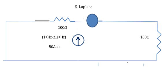
图:3. 包含带电阻器的拉普拉斯开关 (E Laplace) 的高功率网络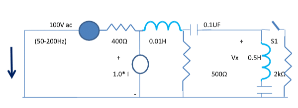
图:4. 带有频率相关开关 S1 的高有效高功率网络
Table III. Frequency description of switch operation (Fig: 3)
| **** 10/14/23 16:46:40 ****** PSpice Lite (October 2012) ****** ID# 10813 **** |
| Frequency-dependent switch simulation |
| Circuit description |
| Voltage AC excitation |
| I 0 3 AC 1 |
| R13 0 3 100 |
| E34 3 4 LAPLACE {I(E34)} = {(ABS(S)/(2.0*3.141592653589793)-1700)*1E8} |
| R40 4 0 100 |
| .AC LIN 13 1KHz 2.2KHz |
| .PRINT AC VM(3) VP(3) VM(4) VP(4) |
| .OP |
| .end |
| **** 10/14/23 16:46:40 ****** PSpice Lite (October 2012) ****** ID# 10813 **** |
| Frequency-dependent switch simulation |
| Small signal bias solution Temperature = 27.000 DEG C |
| Node voltage |
| ( 3) 0.0000 ( 4) 0.0000 |
| Voltage source currents |
| Name Current |
| Total power dissipation 0.00E+00 watts |
| **** 10/14/23 16:46:40 ****** PSpice Lite (October 2012) ****** ID# 10813 **** |
| Frequency-dependent switch simulation |
| Operating point information Temperature = 27.000 DEG C |
| Voltage-controlled voltage sources |
| Name E34 |
| V-source 0.000E+00 |
| I-source 0.000E+00 |
| **** 10/14/23 16:46:40 ****** PSpice Lite (October 2012) ****** ID# 10813 **** |
| Frequency-dependent switch simulation |
| AC analysis Temperature = 27.000 DEG C |
| FREQ VM(3) VP(3) VM(4) VP(4) |
| 1.000E+03 1.000E+02 0.000E+00 1.429E-07 1.800E+02 |
| 1.100E+03 1.000E+02 0.000E+00 1.667E-07 1.800E+02 |
| 1.200E+03 1.000E+02 0.000E+00 2.000E-07 1.800E+02 |
| 1.300E+03 1.000E+02 0.000E+00 2.500E-07 1.800E+02 |
| 1.400E+03 1.000E+02 0.000E+00 3.333E-07 1.800E+02 |
| 1.500E+03 1.000E+02 0.000E+00 5.000E-07 1.800E+02 |
| 1.600E+03 1.000E+02 0.000E+00 1.000E-06 1.800E+02 |
| 1.700E+03 5.007E+01 0.000E+00 4.993E+01 0.000E+00 |
| 1.800E+03 1.000E+02 0.000E+00 1.000E-06 0.000E+00 |
| 1.900E+03 1.000E+02 0.000E+00 5.000E-07 0.000E+00 |
| 2.000E+03 1.000E+02 0.000E+00 3.333E-07 0.000E+00 |
| 2.100E+03 1.000E+02 0.000E+00 2.500E-07 0.000E+00 |
| 2.200E+03 1.000E+02 0.000E+00 2.000E-07 0.000E+00 |
| Job concluded |
如图 3 所示,图 3 中的开关在 1700Hz 时激活,节点 (3) 的电压等于节点 (4)。
Table IV. Frequency description of switch operation (Fig: 4)
| **** 10/15/23 12:27:19 ****** PSpice Lite (October 2012) ****** ID# 10813 **** Frequency-dependent AC switch simulation |
| Circuit description |
| V2 1 0 AC 100 |
| R13 1 2 400 |
| HG1 2 0 V2 1 |
| L23 2 3 0.01 |
| R30 3 0 500 |
| C34 3 4 0.1UF |
| L46 4 6 0.5 |
| C60 6 0 0.1 |
| E45 4 5 LAPLACE {I(E45)} = {(ABS(S)/(2.0*3.14159265359)-150)*1E10} |
| R40 5 0 2000 |
| .AC LIN 4 50 200 |
| .PRINT AC VM(1) VM(3) VM(4) VM(5) |
| .OP |
| .end |
| **** 10/15/23 12:27:19 ****** PSpice Lite (October 2012) ****** ID# 10813 **** |
| Frequency-dependent AC switch simulation |
| Small signal bias solution Temperature = 27.000 DEG C |
| Node voltage |
| ( 1) 0.0000 ( 2) 0.0000 ( 3) 0.0000 ( 4) 0.0000 |
| ( 5) 0.0000 ( 6) 0.0000 |
| Voltage source currents |
| Name Current |
| V2 0.000E+00 |
| Total power dissipation 0.00E+00 watts |
| **** 10/15/23 12:27:19 ****** PSpice Lite (October 2012) ****** ID# 10813 **** |
| Frequency-dependent AC switch simulation |
| Operating point information Temperature = 27.000 DEG C |
| Voltage-controlled voltage sources |
| Name E45 |
| V-source 0.000E+00 |
| I-source 0.000E+00 |
| Current-controlled voltage sources |
| Name HG1 |
| V-source 0.000E+00 |
| I-source 0.000E+00 |
| **** 10/15/23 12:27:19 ****** PSpice Lite (October 2012) ****** ID# 10813 **** |
| Frequency-dependent AC switch simulation |
| AC analysis Temperature =27.000 DEG C |
| FREQ VM(1) VM(3) VM(4) VM(5) |
| 5.000E+01 1.000E+02 2.506E-01 1.243E-03 2.486E-12 |
| 1.000E+02 1.000E+02 2.507E-01 5.048E-03 2.019E-11 |
| 1.500E+02 1.000E+02 2.508E-01 1.132E-02 1.131E-02 |
| 2.000E+02 1.000E+02 2.510E-01 2.151E-02 8.606E-11 |
| Job concluded |
表 IV 显示,在 150Hz 时,开关导通,节点 (4) 的电压转移到节点 (5)。
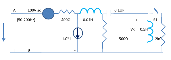
图:5. 带频率相关开关的交流电源电路
图 5 显示了具有电流控制电流源的交流电源电路。表 V 显示了图 5 中开关描述和作的网表。开关用符号 S1 描述。
表 V. 开关运行频率说明(图 5)
| **** 10/15/23 19:35:45 ****** PSpice Lite (October 2012) ****** ID# 10813 **** |
| Frequency-dependent AC switch simulation |
| Circuit description |
| V2 1 0 AC 100 |
| R13 1 2 400 |
| FG1 2 0 V2 1 |
| L23 2 3 0.01 |
| R30 3 0 500 |
| C34 3 4 0.1UF |
| L46 4 6 0.5 |
| C60 6 0 0.1 |
| E45 4 5 LAPLACE {I(E45)} = {(ABS(S)/(2.0*3.14159265359)-150)*1E10} |
| R40 5 0 2000 |
| .AC LIN 4 50 200 |
| .PRINT AC VM(1) VM(3) VM(4) VM(5) |
| .OP |
| .end |
| **** 10/15/23 19:35:45 ****** PSpice Lite (October 2012) ****** ID# 10813 **** |
| Frequency-dependent AC switch simulation |
| Small signal bias solution Temperature = 27.000 DEG C |
| Node voltage |
| ( 1) 0.0000 ( 2) 0.0000 ( 3) 0.0000 ( 4) 0.0000 |
| ( 5) 0.0000 ( 6) 0.0000 |
| Voltage source currents |
| Name Current |
| V2 0.000E+00 |
| Total power dissipation 0.00E+00 watts |
| **** 10/15/23 19:35:45 ****** PSpice Lite (October 2012) ****** ID# 10813 **** |
| Frequency-dependent AC switch simulation |
| Operating Point Information Temperature = 27.000 DEG C |
| Voltage-controlled voltage sources |
| Name E45 |
| V-source 0.000E+00 |
| I-source 0.000E+00 |
| Current-controlled current sources |
| Name FG1 |
| I-source 0.000E+00 |
| **** 10/15/23 19:35:45 ****** PSpice Lite (October 2012) ****** ID# 10813 **** |
| Frequency-dependent AC switch simulation |
| AC analysis Temperature =27.000 DEG C |
| FREQ VM(1) VM(3) VM(4) VM(5) |
| 5.000E+01 1.000E+02 7.143E+01 3.542E-01 7.083E-10 |
| 1.000E+02 1.000E+02 7.144E+01 1.438E+00 5.754E-09 |
| 1.500E+02 1.000E+02 7.144E+01 3.224E+00 3.220E+00 |
| 2.000E+02 1.000E+02 7.147E+01 6.126E+00 2.451E-08 |
| Job concluded |
| **** 10/15/23 19:35:45 ****** PSpice Lite (October 2012) ****** ID# 10813 **** |
| Frequency-dependent AC switch simulation |
| Job statistics summary |
频率相关系统的开关募集因应用而异。可以通过不同的方式评估和比较交换机性能。这些开关可以在设计阶段用于不同的频率范围和功率水平。
频率相关开关配置旨在适应 PSpice 仿真程序,用于电子电路(1700Hz、150Hz)。该开关使用 PSpice 仿真软件在频域中使用四种类型的交流电路进行测试和验证。具有仿真经验的工程师可以实施这些概念设计并满足当今先进的系统要求。